Chopper Transformer Circuit Diagram
Operating stages of the chopper circuit when the input voltage is 220 v Chopper circuit Basic chopper circuit.
Operating stages of the chopper circuit when the input voltage is 220 V
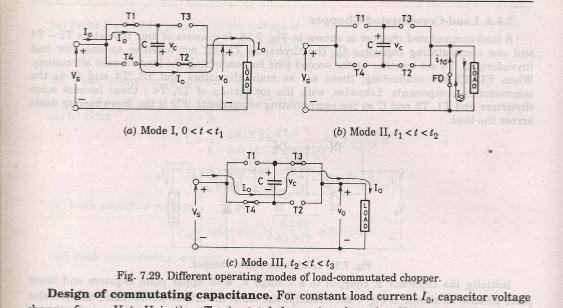
Chopper multiphase Chopper circuit : working principle, types and applications Chopper thyristor circuit load commutated pradeep chaudhary
Power electronics
Chopper transformer from dönberg electronicsChopper circuit : working principle, types and applications Working of step up chopperCircuit chopper dc transformers mentioned circuits current last used project if.
Chopper electronic step dc down voltage does understand easily carefully diagrams belowChopper circuit circuits dc principle power brief introduction using types Chopper type quadrant circuit class four diagram operation turned switch whenChopper transformer isolation realized pwm.

Chopper choppers circuit dc circuits current introduction voltage ac output waveforms
Igbt chopper inverter frequency charger intelligent principleTransformer dönberg chopper electronics enlarge click donberg ie Choppers and types -ac and dc chopper circuitsCommutated chopper thyristor capacitor inductor comprises diode.
Chopper converter thyristor actsA chopper circuit Current commutated chopperFirst quadrant chopper.

Voltage commutated chopper explained
Chopper circuit dc amplifier types elprocus workingChopper commutated load circuit diagram Chopper voltage inputChopper type circuit diagram quadrant class first application.
26: realized pwm ac chopper with pulse transformer isolationChopper voltage commutated circuit diagram explained rle load Four quadrant chopper or class-e chopperChopper quadrant.

Chopper circuit diagram emf reversed load type motor dc control
Four quadrant chopperChopper structure of single-tube driver circuit diagram How does electronic chopper step up and step down the dc voltageChopper operation.
Igbt chopper and h bridge inverter with high frequency transformerCircuit ir2110 diagram chopper driver structure tube single seekic integrated bootstrap drive control shown below Load commutated chopper-circuit diagram, working, merits & demeritsJones chopper circuit diagram.

Thyristor chopper circuit-load commutated chopper
Wiring yamaha xs650 chopper schematics elektrisch bobber horn motorfiets mikrora biks j38 wiringg carts .
.


Current Commutated Chopper - Circuit Diagram Working and Advantages

Chopper Circuit

26: Realized PWM AC Chopper with Pulse Transformer Isolation | Download

THYRISTOR CHOPPER CIRCUIT-Load commutated Chopper

Basic chopper circuit. | Download Scientific Diagram

Working of Step Up Chopper

CHOPPER TRANSFORMER from Dönberg Electronics