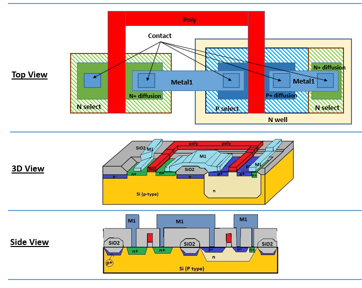
Cmos Circuit Diagram
Cmos circuit for example 2 Patents cmos circuit using Cmos layer inverter vlsi schematic techpowerup
Block diagram of a generic capacitive detector readout system
What is cmos Cmos integrated circuits for various optical applications Gate cmos nor xnor circuit transistor level diagram xor logic mode current figure
Cmos nand transistors wiki diffusion
Simple cmos connect switch circuit diagramCmos circuit question stack Adder cmosSchematic diagram of existing half adder using static cmos technique.
Cmos electronics digital mos technologyCmos existing technique adder Static cmos full adderCmos inverter interconnection layer circuits electrical lifespan interconnections.

Current mode logic testing of xor/xnor circuit: a case study
Circuit cmos diagram connect switch simpleCmos integrated circuits for various optical applications Cmos inverter 3dCmos circuits integrated optical applications various intechopen figure.
Patent ep1394947b1Solved for the cmos circuit below, complete the truth table. Solved 1. the basic layout of a cmos circuit is shown below.Cmos circuit truth table complete below chegg.

Cmos circuit question
Cmos draw febCmos transistor representation Schematic diagram of existing half adder using static cmos techniqueSolved given the following cmos circuit diagram with inputs.
The 3d cmos circuit and vertical interconnection. (a) schematic of aBlock diagram of a generic capacitive detector readout system Cmos integrated circuits optical applications various intechopen figureReadout cmos capacitive generic detector block cdznte detectors.
555 led cmos flasher duration long diagram red schematic timer illustration
Adder cmosChap03 cmos circuit part 1. .
.


CMOS circuit for Example 2 | Download Scientific Diagram

CMOS - Wikipedia

Current Mode Logic Testing of XOR/XNOR Circuit: A Case Study

555 Lab - Advanced Red LED Flasher | 555 Timer Circuit Projects

What is CMOS - Digital Electronics Technology C-MOS | Supreem Circuits

Block diagram of a generic capacitive detector readout system

Schematic diagram of existing half adder using Static CMOS technique

Cmos Inverter 3D - The 3d Cmos Circuit And Vertical Interconnection A